"Guide to Welding Procedure and Welder Qualification as per ASME Section IX"
"Learn the essentials of welding procedures and welder qualifications according to ASME Sec. IX for effective pressure vessel fabrication."

This blog is written to serve as an introduction to ASME Sec. IX. For any details, the code should be referred to Sec. IX of the ASME Code specifies the rules for the preparation of welding procedure specifications and the qualification of welding procedures, welders, and welding operators. This code specifies the rules for all manual and machine welding processes. In the first part of this article, we will see how a welding procedure is to be written and qualified and in the second part, we will see how the welders are qualified. Throughout this article, only shielded metal arc welding (Manual Arc Welding) and Gas Tungsten Arc Welding (TIG Welding) will be considered.
Before we proceed, we shall see how the materials and the filler metal (electrodes and filler wires) are grouped in this code.
MATERIALS
All the materials that can be used for pressure vessel
manufacture have been grouped under different 'P' numbers. The object of
grouping the base materials is to reduce the number of qualifications required.
The 'P' number grouping of materials is based essentially on comparable metal
characteristics such as composition, weldability, and mechanical properties.
The grouping does not mean that the base metals may be indiscriminately
substituted for a base metal which was used in the qualification test without
consideration of the metallurgical properties, post-weld heat treatment,
design, mechanical properties, and service requirements. The 'P' number
groupings are as follows:
P1 to P11 - Steel and steel alloys
P21 to P23 - Aluminum and aluminum base alloys
P31 to P35 - Copper and copper base alloys
P41 to P45 - Nickel and nickel base alloys
P51 to P52 - Unalloyed titanium
For example, SA 106 Gr. A & B pipes, SA 210 Gr. A1, and
SA 515 Gr. 70 plates are all P1 materials. SA 213 Gr. T2 and SA 299 Gr. T11
tubes and SA 335 Gr. P11 and P22 are all P4 materials. All austenitic stainless
steel are P8 materials.
FILLER METALS
The filler metals are grouped under both 'F' numbers and
'A' numbers.
F NUMBERS
All the electrodes and filler rods are grouped under
different 'F' numbers. The object of the 'F' number grouping is to reduce the
number of welding procedure and performance qualifications. The 'F' number
grouping is based essentially on their usability characteristics, which
fundamentally determine the ability of the welders to make satisfactory welds
with a given filler metal. For example, the austenitic stainless steel
electrodes have been grouped under 'F' number 5 and the rutile mild steel
electrodes under 'F' number 2. Obviously, a welder who is able to produce a
sound weld with an E6013 electrode may not be able to produce a sound weld with
a stainless steel electrode. The skills required to use both these electrodes
are definitely not the same.
The 'F' number grouping is as follows:
1 to 6 - Steel and steel alloys
21 to 24 - Aluminum and aluminum base alloys
31 to 36 - Copper and copper base alloys
41 to 44 - Nickel and nickel base alloys
51 - Unalloyed titanium
A NUMBERS
Apart from classifying the filler metals under 'F' numbers,
they are again classified under 'A' numbers. The 'A' number classification of
the filler metals is based on the weld metal chemical analysis, whereas the 'F'
number classifications are based on the usability characteristics. With these
definitions of 'P' numbers, 'F' numbers, and 'A' numbers, now we shall see what
the code says regarding welding procedures and welders' qualifications.
PART-I: WELDING PROCEDURES
The code says that all the details of the welding procedure
should be listed in a document known as a "Welding Procedure
Specification" (WPS). Each of these welding procedure specifications
shall be qualified by the welding of the test coupons, and the testing of
specimens as required in this Code. The welding data for these test coupons and
the results of these tests shall be recorded in a document known as the "Procedure
Qualification Record" (PQR). A WPS may require the support of more
than one PQR, while alternatively, one PQR may support a number of WPS. A WPS
will be applicable equally for plate, pipe, and tube joints. Now, we shall see
how a welding procedure specification is written. The WPS should contain the
following points in detail:
JOINT DETAILS
The groove design, the type of backing used, etc., are to
be specified in this. If a change in the type of edge preparation (Single V,
Single 'U' or double V, etc.) is made or if the joint backing is removed, a
new WPS has to be written but need not be qualified by a test.
BASE METALS
The base metal (P) number and the thickness ranges for
which the procedure is applicable, etc., have to be mentioned here. If the
range of thickness has to be increased or a change of base metal from one 'P'
number to another 'P' number, a new WPS should be prepared and specified by a
PQR.
FILLER METALS
The details of the electrodes, consumable inserts, and
filler wires have to be specified here. The 'F' number, 'A' number, and the
type of the filler metals have to be specified here. The electrode flux
composition (Basic, rutile, etc. also has to be mentioned). A change in 'F'
number or 'A' number shall require a new WPS and PQR. A change in the diameter
of the electrode also requires a new WPS but need not be qualified by a test.
The addition or deletion of a consumable insert or the addition or deletion of
filler metal requires a new WPS & PQR.
POSITION
The positions in which the welding should be done shall be
mentioned here. The qualification test can be done in any position, but still,
the procedure is applicable to all positions.
PREHEAT
The preheat temperature, interpass temperature, etc., shall
be clearly specified. If the preheat is to be decreased by more than 55°C, then
a new WPS has to be prepared and qualified by a test.
POST WELD HEAT TREATMENT
The temperature and time of the post-weld heat treatment
shall be shown here. Any change in this shall require a new procedure
qualification.
ELECTRICAL CHARACTERISTICS
The type of current (AC or DC), polarity, amps, and
voltage, etc., has to be indicated here.
GAS
The shielding gases, flow rate, details of gas purging,
etc., will be shown here.
TECHNIQUE
The details of the welding techniques, string or weave
bead, method of initial and interpass cleaning, back gouging, single or
multiple passes, root grinding, etc., shall be written here.
Once a welding procedure specification has been written,
then they shall be qualified by welding a test coupon and conducting the tests
as required in the code. The test welding can be done either in a plate or pipe
material and in any position. The maximum thickness for which the procedure is
applicable is generally twice the thickness of the test plate or pipe. The
welder who welds the test joint is also qualified for that procedure but only
in that position in which he welds whereas the procedure is qualified in all
positions. The result of the test shall be recorded in PQR.
PART-II: WELDER'S QUALIFICATION
The objective of the welder's qualification test is to
determine the ability of the welders to make sound welds. The welders may be
qualified based on the results of the mechanical tests (one face bend and one
root bend test or two side bend tests) or by radiographic examination of a
minimum length of 150 mm for the plate or the entire weld for the pipe.
The positions of the weld joint have been classified as 1G,
2G, 3G, 4G, 5G, and 6G as shown in the sketch. The following chart shows the
positions qualifying for other positions.
Test Position Also
Qualifies
1G 1G only
2G 1G
3G 1G
4G 1G & 3G
5G 1G & 3G
2G & 5G All
positions
6G All positions


For positions 1G and 2G (Flat and Horizontal), a
qualification on a plate shall also qualify the welder in the pipe. For all
other positions, qualification on the pipe shall qualify for the plate but not
vice versa. A welder qualified in the pipe 6G position is qualified to do
welding in the pipe and plate in all positions. A qualification in a plate or
pipe butt joint shall also qualify the welder for fillet welding in all plate
thicknesses and pipe diameters.
The type of edge preparation and dimensions of the test
joint shall be the same as that for any qualified WPS. If a welder fails in any
tests and an immediate retest is made, the range of thickness qualified is as
follows:
PLATE TRANSVERSE BEND TEST

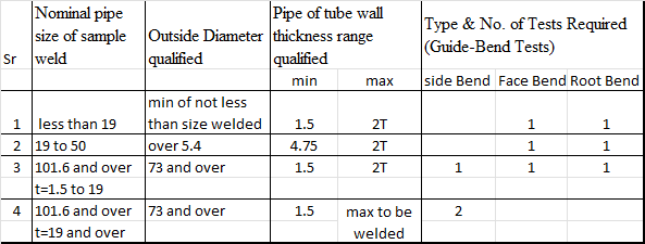
PIPE TRANSVERSE BEND TEST
A welder shall require requalification whenever a change is made in any one of the following welding parameters.
- If a welder had qualified for a WPS with a backing ring and if the backing is removed then he has to pass the test joint without backing. If a welder has qualified for a WPS without backing then he is qualified for a WPS with backing also.
- A change from one 'F' number to another 'F' number of electrode or filler wire, or the addition or omission of a consumable insert shall require a new qualification.
- In gas tungsten arc welding (TIG) a change from AC to DC or vice versa or a change from SP to RP or vice versa shall require a new procedure qualification.


Comments
Post a Comment