Understanding and Explaining Engineering Drawings of a Shell and Tube Oil Cooler
Intricate Details of Engineering Drawings for a Shell and Tube Oil Cooler
Shell and tube heat exchangers are pivotal in industrial
heat transfer applications. This blog post will guide you through the intricate
details of reading and understanding the engineering drawings of these
essential devices, focusing on oil coolers.
Components and Structure
Shell and tube heat exchangers consist of several key components: the shell, tube bundle, tube sheets, baffles, and end caps. Each part plays a crucial role in the heat transfer process and the overall functionality of the exchanger.
Reading the Engineering Drawing

Overview
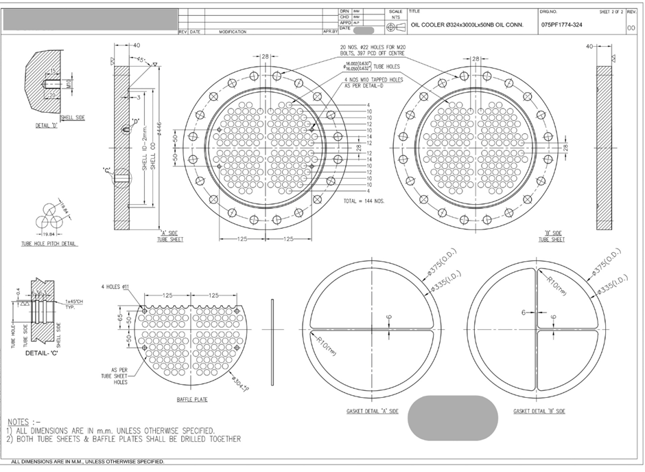
The document shown above is an engineering drawing of a Shell
and tube oil cooler.
Engineering drawings typically use multiple views to represent the object.
Let's start with the title block and general information.
1. Title Block and General Information
The title block usually contains critical information about the drawing, such as:
Drawing Title: Identifies the component or assembly.
Drawing Number: A unique identifier for the drawing.
Date: When the drawing was created or revised.
Drawn by / Checked by / Approved by: Names or initials of
the responsible personnel.
2. Views and Projections
The drawing should include several views:
Front View
Side View
Cross sectional View
Detailed View
These views help in visualizing the oil cooler from different angles.
3. Tables and Charts:
Design Data
Material of Construction
Components item thickness
Nozzle schedule
Special Note
Let's begin by examining the drawing to extract key
measurements and specifications.
Detailed Breakdown of the Oil Cooler Drawing
Shell Dimensions
Length of Shell: 3000 mm [Including both side tube sheet thickness, Tube sheet to tube sheet dimension]
Thickness of Shell: 8 mm [Shown in the table given at
bottom of drawing sheet 1 of 2, mentions item numbers and their respective
thickness]
Diameter of Shell: 324 mm [Outside Diameter] This is 12” seamless
pipe.
Material of Construction: SA 106 Gr B Sch 30[Seamless Pipe Material]
shown in material chart of drawing sheet 1 of 2.
Tube Specifications
Number of Tubes: 144 Numbers [Shown in tube sheet drawing sheet 2 of 2]
Outer Diameter (OD) of Tubes: 15.9 mm [Specify OD]
Tube Gauge: 1.65 mm thk [some drawings Specify it as 16 BWG
which is 1.65 mm thk]
Material of Construction: SA179 C.S.[Carbon Steel Material]
shown in material chart .
Additional Details – Tubes are plain tubes
Tube Sheet Specifications
Number of Tubes: 144 Numbers
Outer Diameter (OD) of Tube Sheet: 446 mm x 40 mm finish thickness
Tube Hole Size: 16.002 to 16.050 mm [16.002 mm is Go gauge size and 16.050mm is No
gauge size for manufacturing and inspection. Thus this is range in between all 144
number of hole should have dimension ]
Material of Construction: SA516 Gr 70 - shown in material
chart .
Tube Hole pitch – 19.84 mm Triangular pitch 60 degree.
Tube Hole Groove- Inside double groove of 3mm wide x 0.04
mm deep x 6mm spacing in between second groove starting at 6 mm from outer
surface of tube sheet as shown in detail C
Pitch Circle Bolts – 20 number holes of 22 mm diameter to
suit M20 bolts on 397 mm PCD Off center.
Tapped holes – 4 number M10 blind tapped holes 15mm deep as
per detail section D for tie rods. This is only on A side tube sheet. B side
tube sheet do not have these tapped holes.
Groove for shell – Shell Id minus 2 mm i.e. 306 mm ID and 324
mm OD groove to insert shell in it for shell to tube sheet joint welding.
Baffle :- 26 number baffles of CRCS sheet 1.6mm thickness of 304 mm OD Spacing at 100mm typical first baffle starting with 250mm from B side tube sheet.
Oil -Inlet and Outlet Dimensions: Nozzle schedule chart
shows oil Inlet and oil outlet 50NB Sch 40 pipe
Water -Inlet and Outlet Dimensions: Nozzle schedule chart
shows water inlet and water outlet 65NB Sch 40 pipe with flanges ANSI B16.5
Class 150
Type of Dish End Caps: Ellipsoidal 2:1, Material 8 mm
thickness SA516 Gr 70
Girth Flanges: Both side girth flanges 48 mm finish
thickness of 446 mm OD of SA516 Gr70 material.
Tie Rods: size M10 with lock nut , material A36
Spacer Tube:- Size 16mm OD x 1mm Thk Tubes, Material Sa 179
Fasteners: M20 Hex bolts with nut and spring washer , quantity
40 numbers, material SA193 Gr B7
Gasket : AF-120 mm material of 3 mm thickness as per sketch dimension shown in drawing sheet 2 of 2. A side and B side gasket are different as suitable for four pass water flow.
Tube Expansion Detail : Length of expansion is tube sheet thickness less 3 mm
Design Data:
Design Code: ASME Sec VIII Div 1 and TEMA.
Fluid : shell side Oil+R717 and tube side – water
Design Pressure: shell side 21 kg/cm2 (Gauge) and tube side
10 kg/cm2 (Gauge)
Design Temperature: shell side 100 degree Celsius and tube
side 60 degree Celsius
Test Pressure: shell side 23.1 kg/cm2 (Pneumatic -by Dry
Nitrogen) and tube side 13.5 kg/cm2 (Hydrostatic- by water)
By breaking down each section of the drawing, you can
understand the design and specifications of the oil cooler. This detailed
explanation can be used to interpreting engineering drawings of shell and tube
heat exchangers.
Thanks for Reading!
https://en.wikipedia.org/wiki/Shell-and-tube_heat_exchanger
https://heatexchangerpressurevessel.blogspot.com/2024/06/understanding-pressure-vessel.html
Let me ask you few question to you :-
How many water passes are in this drawing? and how do you find it in drawing?
You can comment below . Happy Learning !😕


Comments
Post a Comment